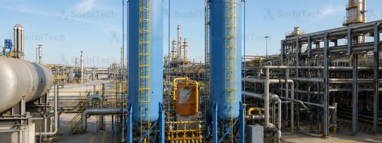
Twin Tower TSA Gas Dehydration Unit
Continuous duty temperature swing adsorption dehydration package for natural gas, engineered by SorbiTech to ASME VIII and PED, with an integrated regeneration heater and cooler.
A Twin Tower TSA Dehydration Unit uses two molecular sieve beds that take turns. One vessel dries the gas while the other is regenerated with hot purge gas, so the unit dehydrates natural gas without interruption. A typical design reaches outlet water dew points below minus 40 °C at pipeline pressure.

Continuous Dehydration on a Swing Cycle
The SorbiTech Twin Tower TSA Dehydration Unit dries natural gas to a guaranteed water dew point on a continuous temperature swing adsorption cycle. Two molecular sieve adsorbers run 180 degrees out of phase: while one vessel is on adsorption at line pressure and temperature, the other is in the regeneration sequence of heating, soaking, and cooling. The unit therefore delivers dry gas without interruption, and a third vessel can be added for sour service or for half cycles longer than 24 hours.
The duty is set by inlet conditions and the contracted outlet dew point, which typically falls between minus 10 °C for sales gas and minus 70 °C for upstream of a cryogenic unit. The package is engineered by SorbiTech and is delivered with a single SorbiTech performance guarantee covering the molecular sieve and the equipment together.
Vessel Construction and Internals
The adsorber vessels are stamped to ASME VIII Division 1 or to PED 2014/68/EU, with 316L stainless internals on every wetted surface in contact with the sieve. The pressure shell is carbon steel with a corrosion allowance set by the inlet hydrogen sulphide level and the project life.
Internal distributors are sized for uniform face velocity to avoid channelling at the wall, which is the most common cause of premature breakthrough. A ceramic ball support and a wire mesh hold down keep the bed in place during pressurisation, and an inlet basket prevents the molecular sieve from contacting any liquid carryover that escapes the upstream coalescer.
The Regeneration Loop
A side stream of dry product gas is heated in a direct fired or electric heater to 250 to 320 °C, passed through the off line vessel in counter flow to remove the adsorbed water, then cooled in an air cooler or shell and tube exchanger and returned to the inlet header. The vent stream from the heating stage is condensed to recover water, which is metered to monitor cycle performance.
The cooler returns the regenerated vessel to within 10 °C of adsorption temperature before switchover, so the first hour of the next adsorption cycle is not consumed by residual heat.
Scope of Supply
A complete package engineered by SorbiTech and supplied by SorbiTech includes:
- Twin or triple adsorber vessels to ASME VIII Div.1 or PED, with 316L internals
- Inlet filter coalescer to keep free liquids off the bed
- Regeneration gas heater and air or water cooled exchanger, ATEX or IECEx rated
- Switching valve manifold, fully welded or flanged to specification
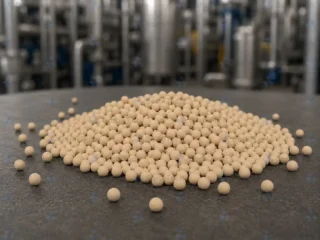
- Media charge of SorbiTech 3A molecular sieve to ISO 9001:2015, loaded under nitrogen
- PLC or DCS sequence control with outlet dew point monitoring and trend logging
Design Data and Sour Service
Capacity from 0.5 to 200 MMSCFD, inlet up to 120 barg, inlet temperature minus 20 to plus 60 °C. Outlet water dew point set per contract from minus 10 °C down to below minus 70 °C. Built to NACE MR0175 and ISO 15156 for sour service in the presence of hydrogen sulphide and carbon dioxide, with hardness controlled welds and post weld heat treatment as required.
Where It Fits in the Treatment Train
The unit covers the duty described under natural gas dehydration, sitting between an upstream inlet separator or gas sweetening unit and a downstream sales gas meter, NGL recovery train, or cryogenic gas plant. For a cryogenic feed the dew point requirement tightens and the bed is sized accordingly.
Sequence Control and Operator Interface
SorbiTech runs the adsorption, switchover, depressurisation, heating, soaking, cooling, and pressurisation steps on a deterministic time base, with override on outlet dew point. A typical PLC architecture is Allen Bradley CompactLogix or Siemens S7-1500 with a hot standby option for critical service, integrated with the plant DCS over Modbus TCP, Profinet, or OPC UA.
The operator interface presents the cycle position, the outlet dew point, the regeneration outlet water rate, and the trend of each vessel temperature against the design curve. Drift on any of those signals is flagged as a maintenance event before it reaches a process trip.
Spare Parts and Lifecycle Support
A typical TSA unit requires planned spare parts for the switching valves, the heater elements, the cooler fan or pump, the inlet coalescer cartridges, and the bed support ceramic balls. SorbiTech holds the recommended two year spares list in stock at the regional service centre and the bed replacement charge of SorbiTech 3A media in a separate inventory reserved against the contracted change out window.
Delivery and Performance Guarantee
Delivered turnkey by SorbiTech or fabricated to client drawings, with civil, mechanical, and electrical scope included where the project requires it. Because the media and the equipment both sit inside the SorbiTech Group, one performance guarantee covers the complete dehydration system from inlet flange to outlet dew point. Long term lifecycle contracts cover media changeouts, valve overhauls, and controls firmware updates inside a single shutdown window. The SorbiTech twin tower TSA package carries natural gas dehydration in the oil & gas sector with 3A, 4A, or 13X media.
Engineered Scope
Project References
Applications This System Serves
-
01
 Process Duty
Beverage Carbon Dioxide Purification
Pellet activated carbon guard bed for beverage grade carbon dioxide purification meeting ISBT (International Society of Beverage Technologists) specifications for carbonated soft drinks, beer,…
Process Duty
Beverage Carbon Dioxide Purification
Pellet activated carbon guard bed for beverage grade carbon dioxide purification meeting ISBT (International Society of Beverage Technologists) specifications for carbonated soft drinks, beer,…
-
02
 Process Duty
Solvent Vapor Recovery
Solvent vapor recovery using twin tower pellet activated carbon adsorbers with steam or vacuum regeneration to capture and recover volatile organic solvents from process…
Process Duty
Solvent Vapor Recovery
Solvent vapor recovery using twin tower pellet activated carbon adsorbers with steam or vacuum regeneration to capture and recover volatile organic solvents from process…
-
03
 Process Duty
LPG and Propane Drying and Treating
Drying and sulphur removal from liquefied petroleum gas (LPG), propane, and butane streams using 3A molecular sieve and impregnated activated carbon to meet pipeline…
Process Duty
LPG and Propane Drying and Treating
Drying and sulphur removal from liquefied petroleum gas (LPG), propane, and butane streams using 3A molecular sieve and impregnated activated carbon to meet pipeline…
-
04
 Process Duty
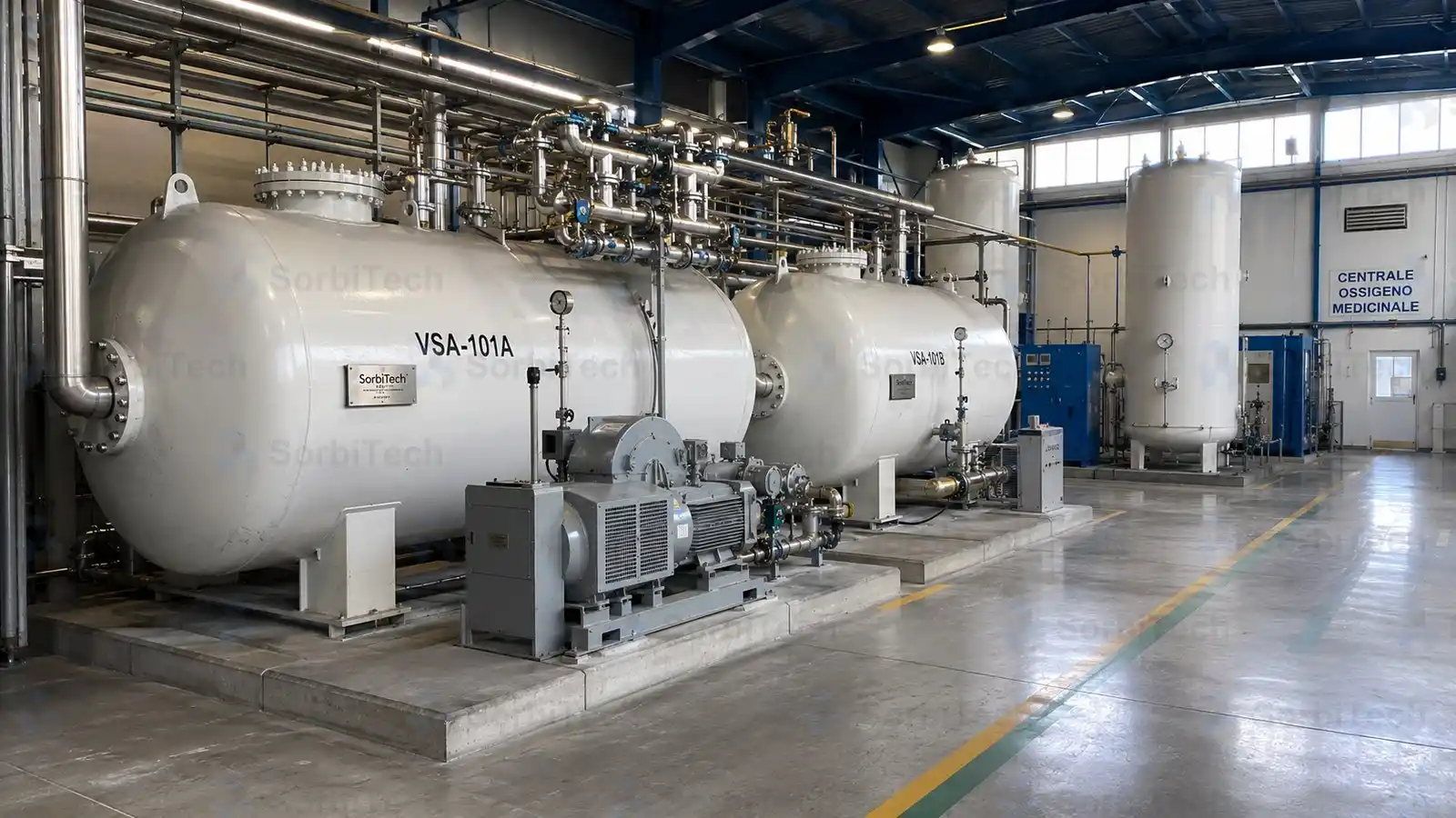
Oxygen Generation (PSA / VSA)
On site oxygen generation by pressure swing or vacuum pressure swing adsorption using lithium exchanged X zeolite for medical, aquaculture, ozone, and metals applications.
Process Duty
Oxygen Generation (PSA / VSA)
On site oxygen generation by pressure swing or vacuum pressure swing adsorption using lithium exchanged X zeolite for medical, aquaculture, ozone, and metals applications.
-
05
 Process Duty
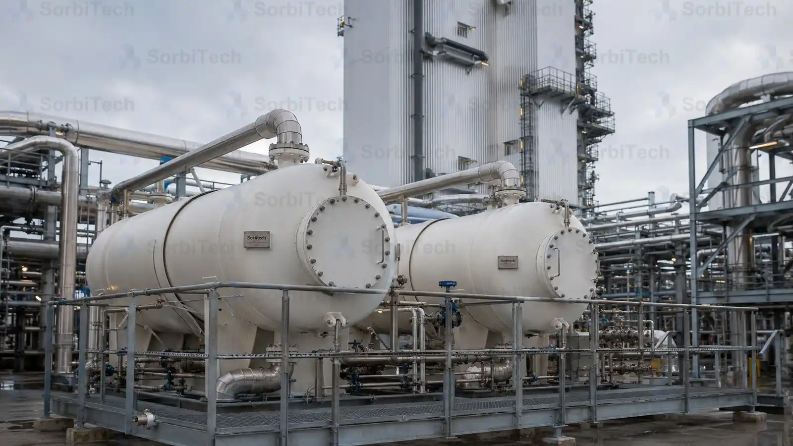
Cryogenic ASU Air Pre Purification
Pre purifying air feed to cryogenic air separation units by removing water, carbon dioxide, and trace hydrocarbons on a graded molecular sieve and activated…
Process Duty
Cryogenic ASU Air Pre Purification
Pre purifying air feed to cryogenic air separation units by removing water, carbon dioxide, and trace hydrocarbons on a graded molecular sieve and activated…
-
06
 Process Duty
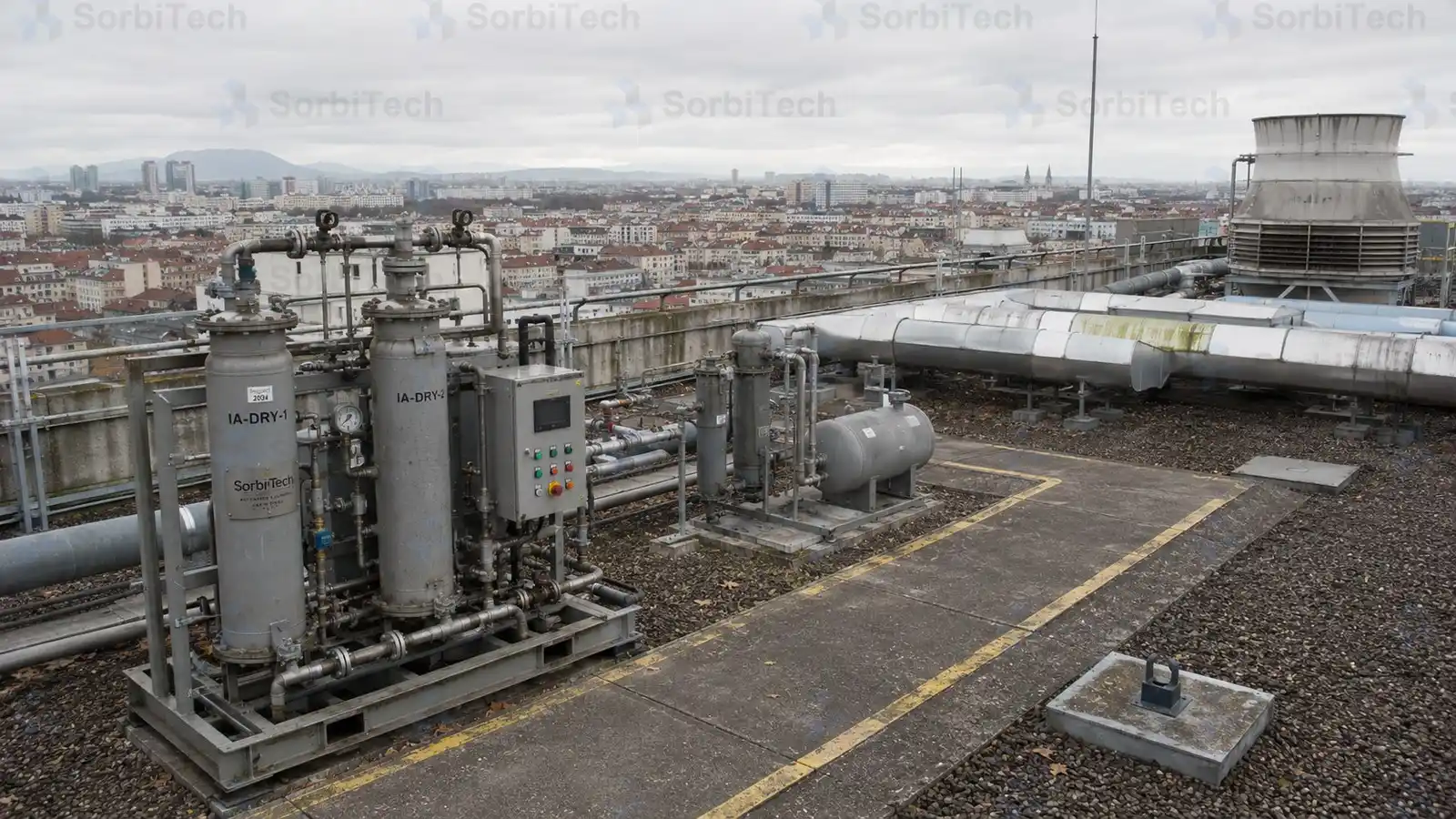
Instrument and Plant Air Drying
Heatless desiccant drying of compressed instrument air and plant air using activated alumina to deliver pressure dew points below minus 40 °C for DCS…
Process Duty
Instrument and Plant Air Drying
Heatless desiccant drying of compressed instrument air and plant air using activated alumina to deliver pressure dew points below minus 40 °C for DCS…
Media Used in This System
-
01
 Adsorbent
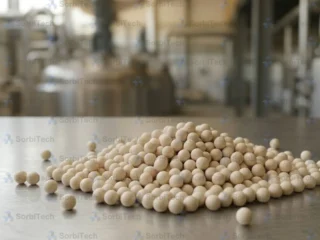
Molecular Sieve 4A
Sodium form 4A zeolite, the standard drying sieve for sweet methane, refrigerant streams, and insulating glass units.
Pore Ø
4 Å
Adsorbent
Molecular Sieve 4A
Sodium form 4A zeolite, the standard drying sieve for sweet methane, refrigerant streams, and insulating glass units.
Pore Ø
4 Å
-
02
 Adsorbent
Molecular Sieve 13X
Sodium form 13X zeolite for cryogenic air pre purification and combined drying and sweetening.
Pore Ø
10 Å
Adsorbent
Molecular Sieve 13X
Sodium form 13X zeolite for cryogenic air pre purification and combined drying and sweetening.
Pore Ø
10 Å
-
03
 Adsorbent
Molecular Sieve 3A
Potassium form 3A zeolite, the size selective desiccant for streams that must not lose hydrocarbons to the bed.
Pore Ø
3 Å
Adsorbent
Molecular Sieve 3A
Potassium form 3A zeolite, the size selective desiccant for streams that must not lose hydrocarbons to the bed.
Pore Ø
3 Å
-
04
 Adsorbent
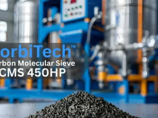
Carbon Molecular Sieve CMS 450HP
Ultra high purity carbon molecular sieve. 99.99999 percent (7N) N2, selective O2 and CO2 capture, 1.0 to 1.6 mm pellets, minimal fines, deoxo polishing…
Water Cap.
Feed must reach ISO 8573 class 1.4.1, deoxo polishing recommended for 7N %
Adsorbent
Carbon Molecular Sieve CMS 450HP
Ultra high purity carbon molecular sieve. 99.99999 percent (7N) N2, selective O2 and CO2 capture, 1.0 to 1.6 mm pellets, minimal fines, deoxo polishing…
Water Cap.
Feed must reach ISO 8573 class 1.4.1, deoxo polishing recommended for 7N %
-
05
 Adsorbent
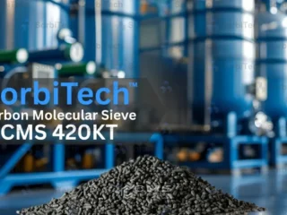
Carbon Molecular Sieve CMS 420KT
High efficiency carbon molecular sieve. Higher oxygen affinity under 7 to 12 barg, 1.2 to 1.8 mm pellets, Snowstorm Filling compatible, ASTM D4058 attrition…
Water Cap.
Feed must reach ISO 8573 class 1.4.1 %
Adsorbent
Carbon Molecular Sieve CMS 420KT
High efficiency carbon molecular sieve. Higher oxygen affinity under 7 to 12 barg, 1.2 to 1.8 mm pellets, Snowstorm Filling compatible, ASTM D4058 attrition…
Water Cap.
Feed must reach ISO 8573 class 1.4.1 %
-
06
 Adsorbent
Carbon Molecular Sieve CMS 350KT
Rapid adsorption carbon molecular sieve. 40 to 90 second cycle at 7 to 10 barg, up to 99.99 percent N2, 1.0 to 2.2 mm…
Water Cap.
Moisture at supply below 1.0 percent, feed must reach ISO 8573 class 1.4.1 %
Adsorbent
Carbon Molecular Sieve CMS 350KT
Rapid adsorption carbon molecular sieve. 40 to 90 second cycle at 7 to 10 barg, up to 99.99 percent N2, 1.0 to 2.2 mm…
Water Cap.
Moisture at supply below 1.0 percent, feed must reach ISO 8573 class 1.4.1 %
Industries Served
-
01
 Sector
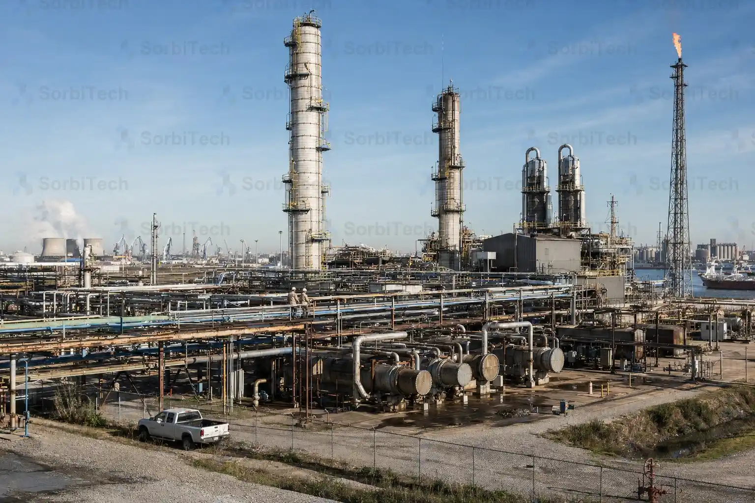
Petrochemicals & Refining
Adsorbents and separation systems for feedstock drying, process gas conditioning, solvent recovery, and refinery effluent treatment.
Sector
Petrochemicals & Refining
Adsorbents and separation systems for feedstock drying, process gas conditioning, solvent recovery, and refinery effluent treatment.
-
02
 Sector
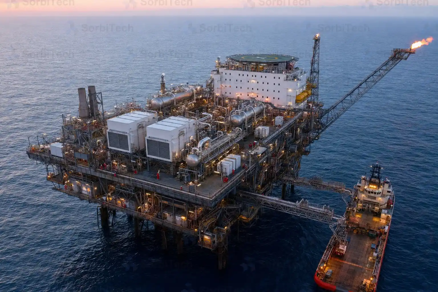
Oil & Gas
Complete dehydration, separation, and treatment across upstream, midstream, and downstream oil and gas. SorbiTech supplies the adsorbent media and the engineered systems from one…
Sector
Oil & Gas
Complete dehydration, separation, and treatment across upstream, midstream, and downstream oil and gas. SorbiTech supplies the adsorbent media and the engineered systems from one…
Discuss Your Engineering Requirements
Our engineers review your duty conditions and recommend the right configuration.